.png)
INSTALLATION & TESTING
This section will go over all of the aspects of installing Pestan PP-R pipe systems including support installation, expansion loop installation, insulation, system care and testing, connections, fusion and repair instruction.
PIPE SUPPORT
There are two types of pipe supports: Continual and Point Support. The support is continual if the pipe is installed in the wall or in a duct or channel. The pipe is point-supported when hangers and clamps are used. When selecting pipe support for your system, it is important to choose products which have been proven safe for use in your given installation. PESTAN
recommends using non-metal hangers and clamps. If they are metal, then the portion that contacts the pipe should be lined to protect the pipe from damage. Be aware that condensation might appear if the metal clamps are used directly on cold pipes. All clamps should be lined with felt or rubber to prevent condensation from happening.
Installer Tip: Prior to finalizing the hanger spacing, run hot water through the pipes to simulate an active system.
Clamp and Hanger Sizing
The following table provides size recommendations for pipe supports. These are based on the pipe’s outside diameter only. If insulating the pipe, total diameter (pipe diameter + insulation thickness) must be taken into consideration.
Note: PESTAN’s Warranty does not cover damage caused by hangers or clamps.
Recommendations of IPS or CTS clamp and hanger sizes suited for equivalent PESTAN pipe size

Support Spacing
General rules apply to the positioning of pipe support for both fixed or sliding points. Maximum support spacing depends on the type of pipe (fiber vs. non-fiber), the pipe’s outside diameter and anticipated temperature difference between ambient and operating temperature of the fluid. Maximum recommended support spacing for PESTAN pipes are shown in the following tables.
Support Interval for the SDR7.4, SDR9 and SDR11 PESTAN pipe with fiber middle layer

Support Interval for the SDR17.6 PESTAN pipe with fiber middle layer

Support Interval for the SDR11 PESTAN pipe without fiber middle layer
(Cold water applications with the ambient temperature below 85°F)

LINEAR EXPANSION AND CONTRACTION
Linear Expansion and Contraction is an important factor when designing a piping system. Pipe expansion and contraction is based on the difference between the ambient temperature and the maximum temperature of the fluid in the pipe.
ΔT = T operating temperature - T installation temperature
When transporting cold fluids, the ΔT value is minimal and the contraction of the pipe caused by the cold fluid will have no impact on the fused connections.
Heat, on the other hand, causes pipes to expand. Typically you will see a greater ΔT value when transporting hot fluids and therefore the system may require compensating additions such as expansion loops and sliding elbows to prevent pipe deformation. PESTAN MECHANICAL pipe with fiber composite helps minimize linear expansion. The Linear Expansion of
the pipe can be calculated using the following formulas:
The linear thermal expansion can be estimated as it follows:
ΔL=α×L×ΔT
Where ΔL is linear thermal expansion inches
α is the coefficient of thermal expansion in/z °F
L is the pipe length z.
ΔT is the change in temperature °F.
For PESTAN PP-R PURPLE pipe made of PP-R:
α = 1.008 x 10⁻³ in/ft. °F
For PESTAN MECHANICAL pipe with fiber composite layer:
α= 2.367 x 10⁻⁴ in/ft. °F
The change in temperature can be estimated as follows:
ΔT = T1 - T2
Where T1 stands for the temperature before the change has occurred °F
T2 stands for the temperature after the change has occurred °F
The 2 tables on below express the linear expansion of PESTAN pipes with composite middle layer and pipes without composite layer.
Linear expansion of PESTAN MECHANICAL Pipes (with Fiber Composite Layer)
PESTAN Pipe with fiber composite has a high level of stability. The linear expansion is decreased to almost 1/5 the value of the standard PP-R and PP-RCT non fiber composite pipes.
Linear expansion ΔL (inches)
Pestan pipes with fiber - α= 0.035 mm/mK = 2.367 x 10⁻⁴"/ft. °F

Linear Expansion of PESTAN PURPLE Pipes
The linear expansion of Pestan PP-R pipe without fiber composite layer are given below.
Linear expansion ΔL (inches)
α = 0.150 mm/mK = 1.008x 10⁻³ in/ ft. °F

Pipe Movement
Based on the application and environment, calculate the expansion or contraction the system will experience. Select the proper pipe supports that will compensate for the movement of the pipe. In concealed installations, installers typically allow enough additional pipe length to compensate for the expansion and contraction. In open installations, it is important that the visual uniformity of the system is maintained. Therefore, expansion loops or sliding elbows are used.
Open Pipe Installation
(including transition through pipe duct)
Both open pipe installation and installation through pipe duct use point support for supporting the pipe. There are two kinds of point supports: fixed and sliding. Fixed points make pipe expansion move to or from the fixed point where sliding points allow pipe movement and expansion through the support without damaging the pipe. Linear expansion has to
be neutralized at one point by branch lines or expansion loops.
Transition Through the Wall
Use only suitable fusion transition fittings. Recommendations are as follows:
Female threaded transition – install outside of the
wall board
Male threaded transitions – flush or outside the wall
Use PESTAN transition elbow 90° for gypsum wall
mounting.

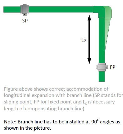
Accommodating Pipe Expansion with Branch Lines

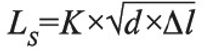
Branch lines at 90˚ angles are used for accommodating pipe expansion. The length of any part of the pipe which is installed perpendicular to the branch and accommodates pipe expansion can be estimated using the following formula:
Where LS is the length of compensating branch.
K is material-specific dimensionless constant
(constant of PESTAN pipes is 2.98 if using Imperial
sizing. When using metric sizing the constant of
PESTAN Pipes is 15)
d is outside pipe diameter in millimeters or inches
Δl is previously estimated longitudinal pipe
expansion expressed in millimeters or inches.
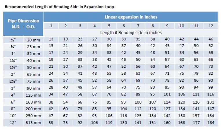
Accommodating Pipe Expansion and Contraction with Expansion Loops

An expansion loop has to be installed if longitudinal expansion with branch lines is not available. For the installation of an expansion loop, four 90 °elbows will be required. Aside from the length of the branch line LS, the width of the expansion loop should be included in the formula. The necessary expansion loop parameters will be analyzed in the following
formula.
Where LS is the length of the compensating branch.
K is material-specific dimensionless constant
(constant of PESTAN pipes is 2.98 or when using
metric sizing the constant of PESTAN Pipes is 15)
d is outside pipe diameter in millimeters or inches
Δl is previously estimated longitudinal pipe expansion in millimeters or inches
It is also important to estimate the width of expansion loop (Amin) using following equation:
Where Amin is the width of expansion loop
Δl is previously estimated longitudinal pipe expansion in inches or millimeters
SA is a safety distance of 6" (152.44 mm)


In order to install compensation elements such as branch lines or expansion loops in limited spaces, the length Ls and
therefore the Amin, can be reduced by pre-stressing the expansion loop. Length of prestressed elements are calculated as follows:
Where LSV is necessary pre-stressing length.
K is material-specific dimensionless constant
(constant of PESTAN pipes is 2.98 or when using
metric sizing the constant of PESTAN Pipes is 15)
d is outside pipe diameter in millimeters or inches
Δl is previously esSmated longitudinal pipe expansion
expressed in inches


Vertical Installation
As fiber and non-fiber pipes have various linear expansion coefficients, the pipe branches are to be installed
on risers according to the selected type of pipe.
With fiber pipe:
When installing risers with PESTAN Fiber Composite pipe, fixed points are positioned next to a branch. The
expansion will be distributed between the fixed points, thus, the linear expansion of PESTAN fiber
composite pipes in vertical risers can be ignored. Generally, risers are installed without expansion joints.
For pipe sizes 2" and below, the space between two fixed points must be a minimum of 10z, and mid-story
guides are recommended.
With non-fiber pipe:
When installing risers with PESTAN pipes without a fiber layer, it is necessary to install branch lines so linear
expansion of the vertical riser can be accommodated. An adequate expansion control must be installed as
described in this section. Because non-fiber pipes have no integrated expansion control, PESTAN
recommends installing fixed points in heated applications before or after each branch line, inhibiting any
movement due to expansion.
Besides the above mentioned methods, pipe sleeves or swing joints can also be used.
INSULATION
Pipes are insulated to prevent condensation and heat loss. One of the benefits of using PESTAN PP-R(CT) is the relatively low thermal transmission coefficient. It significantly improves energy savings as compared to traditional metal piping by reducing the amount of insulation that is required and minimizing condensation. Recommendations on minimum required pipe insulation are made in both ASHRE 189.1-2010 C-11 and in IECC 2012-403.2.8.

Heat Gain and Loss Calculations
PESTAN’s PP-R(CT) pipe have low thermal conductivity (k)* value, especially when compared to metal piping. Metals are considered to be conductors of heat, which results in the loss of energy, lower system efficiencies and increased costs. The following are comparisons of the thermal conductivity (K factors) expressed in BTU/hr-ft-F:
k PESTAN = 0.139 @ 68°F k copper = 227 @ 75°F k steel = 31 @ 75°F
*The thermal conductivity (K Factor) of a material is based on the number of BTUs per hour which passes through a one inch thick by one square foot section of material, with a 1°F temperature difference between the two surfaces. Materials with a lower K-Factor are better insulators.
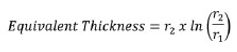
The R-Value is the capacity of an insulating material to resist heat flow. The higher the R-value, the greater the insulating power.
Heat loss or gain characteristics can also be expressed through R-value, which has direct relationship with the
K-values, as shown in the following equations:
Where r1 = Inner Radius and r2 = Outer Radius

Insulation Thickness Calculations
For applications not covered by the tables published by ASHRAE and IECC, the following information is
useful when calculating thermal resistance values and heat loss/gain:
k ins = 0.0208333 (for typical .25" up to 1" closed cell foam insulation)
k ins = 0.02375 (for typical 1.50 up to 2" closed cell foam insulation)
ΔT = 50°F (typical temperature difference between hot water and room temperature)
Heat Transfer Coefficients (BTU/hr-z2-°F/in)
The heat transfer coefficients are affected by factors including average temperature, pipe wall temperature and wind speed. It is calculated by using the Zukauskas Equation and typically falls in the range of 0.5 to 4 (BTU/hr-z2-°F). To calculate, determine the Nusselt number for the set of conditions then calculate the outdoor heat transfer coefficient.
Example:
Air heat transfer coefficient = 2 @ avg. temperature = 100° F, pipe wall temp = 80° F and wind speed at
5 mph.
For this given set of conditions, the heat transfer coefficient: hO = 1.6
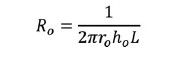
Calculated Thermal Resistance Values (hr f F/BTU)
Rpipe =Thermal resistance of pipe wall Rins = Thermal resistance of pipe insulation
Ro = Thermal resistance of outer air
Where Ro = layer radius and L = length of pipe/insulation


Thermal Resistance cont.
Rtotal = Total thermal resistance of pipe and pipe insulation
Calculated Heat Loss (BTU/hr-z)
qpipe = Heat loss through a non-insulated pipe,
qtotal = Total heat loss through an insulated pipe,
Where ΔT is the temperature difference between ambient temperature and liquid in the pipe.
Note: It is common practice among contractors to install the entire PESTAN piping system first, then to insulate it with specified material.
R-Values (hr f2 F/BTU)
Based on the outside diameter and wall thickness of the pipe


PRE-FORMED INSULATION
The outstanding natural insulating properties of PESTAN pipes helps reduce the amount of insulation required to control heat loss/gain, heat gain and condensation as compared to metal piping systems. Consult code requirements for your particular project to insure that reductions in insulation thickness are allowed.
PESTAN recommends using metric size pre-formed insulation for the pipes. If not available, the chart to the right makes recommendations on which IPS or CTS sizes of pre-formed insulation are best suited for equivalent size.
SYSTEM CARE
Flushing the Pipeline
The piping system should be flushed after installation. It is also highly recommended to disinfect the pipeline as both mineral and organic particles can contaminate the piping system and affect transported fluid. The flushing medium should
be safe for PP-R(CT) material and should be specified under local codes, engineering specifications and/or by the needs of the mechanical equipment used. If no flushing methods are specified then water, air or a mixture of both can be used.
CERTIFICATE OF COMPLIANCE
Pressure test
Pressure testing is critical to a successful pipe installation and should be performed while the system is fully accessible, allowing access to the segments of the system in need of attention. The unique property of PP-R(CT) allows the pipe to be
tested with water, air, or with a mixture of both. Warning: When pressure testing with air, the contractor must exercise extreme caution. Accidents can occur due to a sudden release of energy such as unrestrained sections of pipe whipping about or piping system components blowing off. PESTAN recommends hydrostatic or hydrostatic/pneumatic
testing over pneumatic. During pressure testing, the pipe, fittings and connections must be able to sustain 15O% of the Operating Pressure (OP) or 150 psi, whichever is greater.
Warning: Isolate components of the system with the
ratings lower than 150psi when pressure testing PPR(CT) systems.
150% of OP or 150 psi, whichever is greater = Test Parameter (TP).
The pressurization of the system can affect the physical characteristics of the pipe. The ΔT
(system fluid temperature minus ambient temperature) can cause expansion or contraction. Subsequently, the test results will be influenced by these factors. Various temperatures of the pipe and the test medium will lead to changes in system pressure. Temperature fluctuations of 18° lead to changes in test pressure from 7.25 to 14.5 psi (0.5 to 1 bar). During the pressure test, the highest possible constant temperature of the test medium must be measured. If feasible, let the temperature between the pipes and the test medium reach equilibrium before reading the meter to get the most accurate
results.
The pressure test consists of three phases: Initial, Principal and Final test. Please see page 57 for instructions.
Note: During the testing of large installations, small leaks may take longer to manifest as a pressure loss.
How to Measure Pressure Test
The pressure test must be performed with a pressure gauge that measures in 0.5 psi increments. When testing a multi-story installation, the pressure test should be conducted at the lowest point of the piping system that can be accessed.
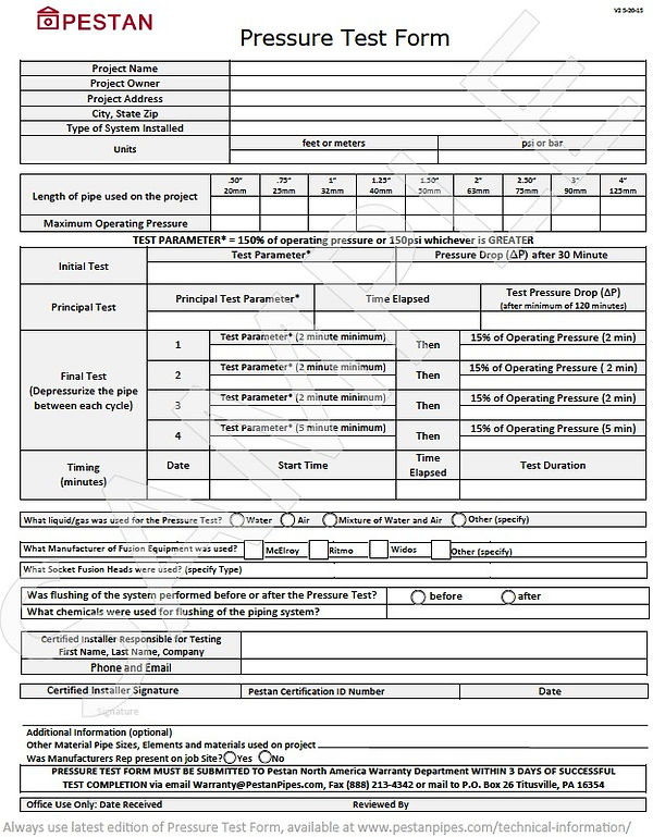
Test Record
All PESTAN installations must be pressure tested and documented on the official PESTAN Pressure Test Form. The Pressure Test is required in order to identify any potential issues including manufacturing defects and installation errors. It is acceptable to pressure test the system in phases providing that every heat fused connection is tested and that each
phase is properly documented on Pressure Test Form. The entire form must be completed and signed by the PESTAN trained installer. Both the client and contractor should keep a copy of the pressure test record. Completion and submittal of the Pressure Test form is required by PESTAN in order for the warranty to be valid. It does not replace any local legal requirements or supersede them. PESTAN requires this test to be performed, documented and submitted before the system becomes operational.

Initial and Principal Test:
1. Initial Test: Bring pressure in system up to 150%
of the operating pressure (OP) or 150 psi,
whichever is greater (Test Parameter = TP).
2. Wait 10 minutes then read pressure. When
system pressure decreases due to pipe
expansion, pressure it back to TP.
3. Repeat step 2 until the system has stabilized.
4. When stable, begin 30 minute test period, then
read pressure. Pressure must not lose more than
9 psi (0.6 bars). If it passes, begin the Principal
Test.
5. Principal Test: Begin the 120 minutes (2 hours)
test period. Pressure must not drop more than 3
psi (0.2 bars) during the two hour period.
6. Once the system has met the requirements of
steps 4 and 5 the final test can be performed.
7. If the system pressure fails to stabilize or fails to
meet the requirements of steps 4 and 5, inspect
the system for possible leaks. Make any
necessary repairs and restart the tesSng process.
Final Test:
1. Bring the system up to 150% of the operating
pressure (OP) or 150 psi, whichever is greater.
(Test Parameter = TP) and wait 2 minutes.
2. After 2 minutes with no pressure loss, reduce
pressure to 15% of OP and wait 2 minutes.
3. After 2 minutes with no pressure loss, drop
pressure to 0 psi.
4. Immediately bring system pressure back up to TP
and repeat steps #2, #3 and #4, four more times.
5. When testing for the fourth time, drop pressure
to 15% OP and wait 5 minutes. After 5 minutes
with no pressure loss, drop pressure to 0 psi.
6. Immediately bring system pressure back up to TP
and wait for 5 minutes.
7. Drop pressure to 15% OP and wait for another 5
minutes. Drop pressure to 0 psi.
8. No leakage is allowed to occur at any point of the
tested installation. This test is designed to expose
any possible cracks and to detect bad pipe
connections.
PRESSURE TEST FORM
CONNECTIONS, FUSION TOOLS,
AND INSTRUCTIONS
TRAINING FOR INSTALLERS
PESTAN offers training to installers via local representatives or through their affiliates. Trained and registered installers are critical for a successful system to be covered under the warranty. When installation is not properly conducted, documented and submitted, the warranty will not be valid. For more information, contact PESTAN N.A.
.
If you have previous experience installing PP-R(CT) piping systems, please contact Pestan North America.
Installation Concept: PP-R(CT) = Savings
PESTAN PP-R(CT) piping systems provide the installer with innovative installation advantages that provide real time savings:
• Ability to prefabricate and transport complex assemblies
• Ability to pre-assemble components on the jobsite
• Lightweight PP-R(CT) provides easier handling, installation and transportation
• Heat Fusion connections are permanent and leak-free.
• Ability to install sidewall outlet connections (used for branching lines, manifolds, repairs, gauge outlets, etc.)
Prefabrication
The ability to prefabricate and transport connections is one of the great advantages of PESTAN piping systems. Instead of having to make all of the complex assemblies on the job site, the installer can prefabricate them at his convenience, in a clean, controlled environment which improves the overall integrity of the system and saves him both time and labor dollars on the jobsite. Because PP-R(CT) piping systems are joined with heat fusion, the prefabricated pieces can be safely transported to the jobsite without having to worry about negatively affecting the integrity of the joints.
Note: Creating a Fabrication Work Space on the job site is another important time saver. It provides a space for the installer to measure, cut and pre-assemble system components. The space needs to be equipped with ample light and adequate power.
Effective Planning
To best utilize the advantages of a PP-R(CT) piping system the installer needs to plan ahead. This will help him to save time and prevent waste. A few tips include:
• Insure you have the required system components on hand.
• Create a convenient space for a work station where pipe can be cut and fabrications can be pre-assembled.
• Plan your connections in advance so you have enough space and flexibility for placement of the fusion machine and for fusing the last connection in a series. Remember to include the additional length of pipe used by heat fusion in your calculation.
• Utilize prefabrication and pre-assembly of components and connections whenever possible.
CONNECTIONS AVAILABLE
PP-R(CT) pipes are joined via Heat Fusion which provides permanent, leak-free joints.
Depending on pipe size, there are three different types of heat fusion processes that are recommended:
• .50" to 4" - Socket Fusion
• >4 - Butt Fusion
• Saddle Outlet Fusion for branching off mains, manifold fabrication, gauge outlets, etc.
PESTAN offers a complete line of fusion fittings for connecting your system . When you need to transition from
your fused piping system to a non PP-R(CT) system or to equipment, metal fittings or valves, PESTAN offers two
options:
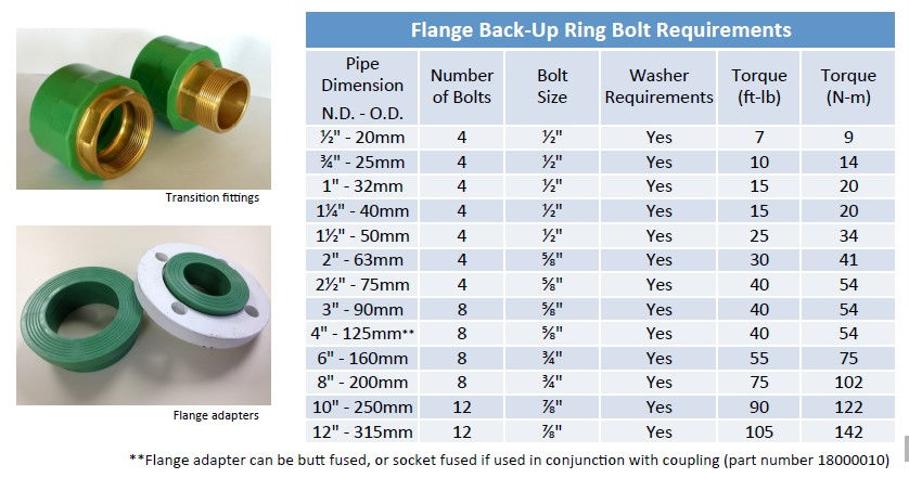
• Transition Fittings are made from injection molded PP-RCT with brass or lead-free brass threads.
• Flange Connections are made using PESTAN’s PP-RCT Flange adapter and a steel back-up ring. PESTAN
recommends using full face rubber gaskets. Ring gaskets are acceptable for lower pressure systems.
FUSION
Fusion of the joint has to be performed according to the guidelines in this manual. More informaSon is available in ASTM D2657 - Standard PracSce for Heat Fusion Joining of Polyolefin Pipe and Fihngs. There are several styles of fusion tools to choose from based on the pipe size, type of fusion and the locaSon of the installaSon. Tools can be categorized as following: Hand-Held Irons, Table Top models and Portable Fusion Machines. The quality of the fusion equipment will affect the quality of the fusions. When fusing PESTAN pipe, we recommend using fusion equipment by recommended manufacturers that are strictly designed to follow the DVS 2208
standard.
Note: PESTAN assumes no responsibility when connections are made using faulty and/or nonstandard equipment. For recommended fusion equipment please visit our web site at www.pestanpipes.com/tools-and-accessories/
Preparation for fusion utilizes the same basic steps regardless of which fusion tool is used. It includes the following basic steps: Safety, Power Supply, Tool Preparation, Marking and Pipe Preparation.
Safety Measures
When conducting heat fusion, you are handling tools, pipe and fittings that are heated to temperatures up to 500°F. It is extremely important that safety guidelines be followed.
-
Only persons certified in heat fusion should conduct fusions.
-
Always wear the applicable safety clothing which may include: safety glasses, long sleeves, gloves, safety shoes and a hard hat.
-
Be aware of your environment and verify that it is a safe space to operate fusion equipment.
-
Understand proper operation and safety procedures for the fusion equipment you are using.
-
Insure all fusion tools are in good working order.
-
Never leave heated fusion tools unattended.
-
When unplugged, fusion tools should be properly stored.
-
When using electric fusion tools, follow recommended electrical safety practices.
-
Never start the fusion process without posting a warning sign.
Power Supply
The power supply needs to be compatible with the fusion iron. Insufficient power supply can cause cold fusions that will fail. If using extension cords, insure that cord is capable of delivering the required power and that you are within a reasonable distance from the power supply.
Tool Preparation
1. Assemble the required socket fusion tools.
2. Verify that the fusion heads and cold ring (if used) are compatible with the pipe size.
3. Make sure that the iron and socket heads are clean and free from any contaminants. If dirty, clean with a soft cloth and alcohol, taking care not to scratch the Teflon coating.
4. Attach the fusion heads to the fusion iron insuring full surface contact between the head and the iron.
5. Connect the heating tool to the power supply.
6. Pre-heat the iron to 480-500°F (248-260°C).
7. Verify that the temperature on the fusion head has reached 480-500°F (248-260°C). Use of Tempilstiks, or any other thermal detection devices are recommended in addition to the tool indicator light or gauge on the fusion tool.
Pipe Preparation
Follow these steps to prepare the pipe for fusion:
1. Make sure that the pipe length has not been damaged. Double check the pipe ends which are more susceptible to damage. If damage is noted, remove the damaged section of the pipe.
3. Measure and mark the length of pipe.
4. Use pipe supports when cutting to prevent pipe movement.
5. Wear eye protection when cutting the pipe.
6. Use ratchet cutters with a sharp blade. A dull blade can affect the ovality of the pipe.
7. Use hand wheel cutters for larger diameter pipe
8. If using a handsaw, the teeth should be safe for plastic.
9. Band saws and reciprocating saws may be used. Thinner blades produce a better cut with fewer shavings.
10. When using electric saws, use a circular hardwood blade with carbide teeth (60 -100T). Note: Do not use circular saws if the ambient temperature is less than 40°F
SOCKET FUSION
(using Hand-Held Irons)

Socket Fusion - Marking
When performing socket fusion, there are two methods to determine how far the pipe should be pushed onto the fusion iron. You may use a recommended marking guide or use the chart below to reference the appropriate stab depth and then use a measuring tape to mark it on the pipe. Mark required depth on several places around the pipe for insertion depth guidance.

Socket Fusion – Heating Pipe and Fittings
When the heating iron has reached 480-500°F (248-260°C), you may begin the heating process. When socket fusing, you will be heating the outside of the pipe and the inside of the fitting.
-
The pipe and fitting are simultaneously pushed (no twisting) on to the fusion head which is attached to the heating iron.
-
As the pipe and fitting soften, you will be able to push them further on the fusion head.
-
When you reach the point on the pipe that you marked, stop pushing.
-
Continue to push the fitting until it reaches the base of the fusion head.
-
The heating time starts when both the pipe and fitting have reached their maximum insertion points.
Socket Fusion – Heating Time
The following heating times are recommendations based on ambient temperatures above 40°F (for requirements and instruction of installations in environments under 40°F, please contact us). Actual required heating times may vary based on ambient conditions, continuity of power supply, etc. PESTAN recommends that you perform a test fusion in order to identify optimum heating times.
Socket Fusion – Joining the Pipe and the Fitting
Once the Heating Times have been met, remove the
pipe and fitting from the fusion head. Do not twist
them off, pull them straight away. Quickly inspect
the melt on both. Align the pipe with the fitting and
insert the end of the pipe into the fitting until the
bead on the pipe touches the edge of the fitting. Do
not twist the pipe or fitting. This can displace the
molten material and affect the integrity of the joint.

Socket Fusion - Correction Time
Once the pipe has been inserted into the fitting, you
have a few seconds during the Fusion Time to adjust
the angle of the pipe up to 10° in order to properly
align it with the fitting.
Socket Fusion – Fusion Times
Once the pipe has been inserted into the fitting and
any required corrections have been made, the
connection must be held in place until the joint cools
and the fusion is set. Recommended Fusion Times are
given in the table below, based on pipe size and may
vary based on ambient temperatures.

Socket Fusion - Cooling Times
After the Hold Time has been met, the joint should be allowed to rest for a few more minutes before use.
The following are Cooling Time recommendations. Do not try to accelerate the cooling times by using water.
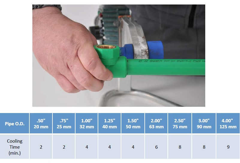
After the cooling times have been met, the joint is ready for use. Socket fusion results in a perfect bond of
the pipe and fitting.
Recommendation
For the socket fusion under 2” the use of a chamfer
tool with depth gauge along with cold rings is
recommended. Chamfer tool already has set Stab
Depth, so cold ring should be set right next to it
after chamfering has been done. Using cold rings, it
makes socket fusion square and keeps installer
hands away from the iron, preventing the burning.
Note:
Metric cold rings and
chamfering tools are
available exclusively
through CT Piping.


SADDLE OUTLET FUSION
(using Hand-Held Irons)
With Socket or Butt Fusion, the end of the pipe is being heated and fused. With Saddle Outlet Fusion, the fusion
welds are in the wall of the pipe as well as on the curved surface of the pipe and fihng. This makes it ideal for
installing branch lines off the main, manifolds, insertion of the gauges, etc. These connections can even be made
after the main lines have been installed. Using saddle connections when building manifolds saves fabrication
time and money. Also, saddle connections have lower pressure loss than a reducing tee.
The following table shows whether a regular and threaded saddle is available for a particular branch size:


Saddle Outlet Fusion – Preparation
Before you begin the Saddle Outlet Fusion process, follow the Basic Preparation Steps outlined in the fusion section above.
Mark the location of the bore on the wall of the pipe. When drilling the outlet bore, Pestan recommends using a
a special bit that is designed to take out the cuttings created during the boring process. PESTAN offers drill bits
for making precise bores in the pipe wall. If the drill bits are larger than 2", a drill press is required. When using
bits supplied by companies other than PESTAN, make sure they are between 1 mm to 3 mm smaller than the
branch size.
It is important to drill at a precise 90° angle. The fusion heads must fit flush against the pipe. Double-check to
ensure that no extra material or burrs are left inside the pipe once you have drilled the hole. Make sure to
remove any pipe shavings that are still attached.

Saddle Outlet Fusion - Heating Process
Verify that the temperature on the fusion head has reached 480-500°F (248-260°C). Insert the heating tool into the borehole of the pipe.
Use a wooden dowel or other heat resistant device to push down on the heating tool, melting it into the borehole.
When the fusion head is completely inserted into the borehole, place the saddle fitting on the fusion head and apply pressure. Be careful not to move or twist the heating tool.
When the saddle fitting is completely on the fusion head, until you can see an even melt all the way around (approx. 30 seconds).
When the heating time is met, pull the heating tool straight out of the borehole and the saddle fitting straight off the fusion head. Do not twist off.

Saddle Outlet Fusion - Connecting the Fitting to the Pipe
As soon as you remove the saddle fitting from the fusion head, insert it vertically into the borehole. Do not twist
the fitting into the borehole. Twisting the fitting can displace the molten material and affect the integrity of the
fitting. Immediately check the placement of the fitting on the pipe and use a level to insure it is placed properly.
The installer has only a couple of seconds to correct the position of the saddle.

Saddle Outlet Fusion – Fusion Times and Cooling Period
Once the fitting has been installed on the pipe and any required corrections have been made, the connection
must be held in place until the joint cools and the fusion is set. After 10 minutes, the connection is ready to
operate under pressure.
PIPE REPAIR TECHNIQUES
If PP-R(CT) pipe is punctured by a nail or screw, the pipe can be repaired. For holes that are 3/8" or less in
diameter, you may use a repair pin. For larger punctures, repair with saddles.
Repair Pin
1. First assemble the tools required for making the repair. Attach the fusion repair head onto the fusion iron.
2. Connect the fusion iron to the power supply.
3. Remove the penetrating object from the pipe and clear the hole.
4. The repair head comes in two sizes: ¼" and 7/16". If the hole is too small then the installer should drill it out with a 3/16" bit for the ¼" repair tool or a 3/8" bit for the 7/16" repair tool. If the hole is larger than the 7/16" repair tool, then a saddle repair should be done.
5. Wipe away any dirt or debris and insure that the pipe is completely dry.
6. Mark the repair pin to the appropriate depth of insertion, which is equal to the thickness of the pipe wall. If you are unsure of what this thickness is, refer to the pipe dimension table on pages 79 to 82. You may also compare it to a piece of uninstalled pipe of the same diameter and DR.
7. When the fusion repair head has reached 480-500°F (248-260°C), insert the repair pin into the repair head and insert the repair head into the hole in the pipe.
8. Heat both the hole and the pin for 5 seconds.
9. Remove the fusion repair head and insert the repair pin into the hole to the pre-marked depth of insertion. Do not twist.
10. Hold the pin in place.
11. Once the pin has set, remove the unused portion of the Repair Pin by carefully holding the end of the pin in place while cutting it with pipe cutters or construction knife. Use caution when doing this and be sure that your fingers are clear of the cutter blade.
12. Pressure test the system following the repair.


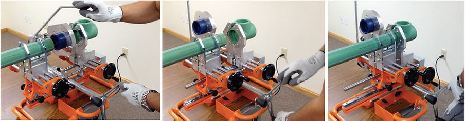
SOCKET FUSION ASSISTED BY FUSION MACHINE
For the socket fusion connections of 2" and above, it is recommended to use the assistance of Fusion Machines.
Using fusion machines will help installers with faster and more precise connections. There are three major types
of fusion machines: Jig, Portable and Bench machines, all using same principles and procedures of fusion.
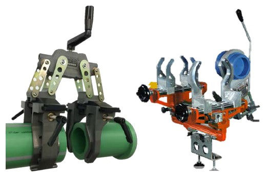
Jig and Portable Fusion Machine
Portable fusion machines and Jigs are mobile and are designed for jobsite fusion connections of 2" and above. They can be freestanding or fastened to available surfaces and used in a pre-fab station. These units consist of a sliding carriage with a light metal body, a built-in or removable heating plate, clamping jaws and mounting clamp. These types of fusion machines are ideal for vertical, overhead and tight space installations.
Bench Fusion Machine
Bench fusion machines are designed for socket fusion connections of 2" and above. These machines assist the installer by holding the pipes in place making for precise and consistent fusion joints. They are available in both tabletop and portable models.
When using either a stationary or portable Socket Fusion Machine, it is important that you follow all safety, maintenance and operational guidelines set forth by the equipment manufacturer. Fusions done with Socket Fusion Machines follow the same basic fusion preparation steps as those done with hand-held machines. PESTAN recommends that prior to making a system connection, the operator conducts a test fusion to verify that the machine is in proper working order.


JIG-ASSISTED SOCKET FUSION
Jig’s light and compact design, allows installers to accomplish connections in tight spaces or while working on overhead installations. Furthermore, jigs can be used on the ground as the prefabrication station for uniform and consistent connections. When performing jig-assisted socket fusion, follow all safety measures and recommendations on page 61.
Verify the fusion heads are compatible with the pipe and fitting size. Install the fusion heads on the heater face.
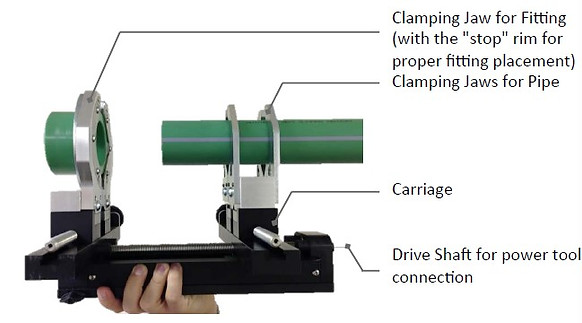
Plug the fusion tool into the power source and verify the temperature of 480 - 500˚F (248 - 260˚C) has been reached. Cut the pipe to the desired length. Measure and mark the insertion depth (page 68) on the pipe in multiple points around the pipe O.D.
Place the end of the pipe to be fused in the smaller set of clamping jaws. Make sure that the measured insertion mark is ½" to 1" beyond the edge of the clamping jaws. Place the fitting in the larger jaw flush with the integrated stop rim. Make sure that pipe and fitting are tight enough to prevent movement. Use a drill to move the carriage forward and backward.
NOTE: Do not leave the drill hanging from the jig after use. In order to check for alignment and proper spacing, advance the carriage forward so that the pipe and fitting are in the proper position for fusion.

Reverse the carriage, backing the pipe and fitting apart, so that the fusion iron can be inserted between them. Insert the fusion iron. Advance the carriage forward moving the pipe and fitting into the fusion head. Continue to advance until the marked insertion depth is reached. When fusing larger pipe diameters, it is recommended to advance the carriage in short bursts, allowing the fusion heads to melt the pipe and the fitting.

Refer to the table for fusion heating times in the previous section. The heating time starts when the pipe and fitting are completely inserted in the fusion head.
When the heating time is met, reverse the carriage moving the pipe and fitting away from the fusion iron. When removing the iron, do not twist but pull the iron straight away from the pipe and fitting, being careful not to damage the fusion bead or disturb the melt. Set the fusion iron back on its stand. Immediately advance the carriage forward, moving the pipe and fitting together until the pipe is inserted into the fitting. Do not over-insert (stop when the melted beads meet).

The pipe remains in this position until cooled. Refer to the recommended cooling time table in the previous section.
BENCH AND PORTABLE FUSION MACHINES
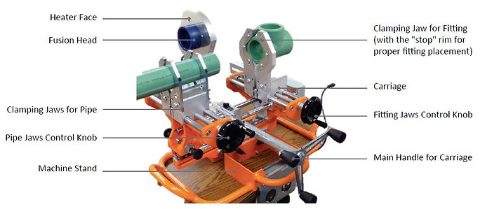
Clear the surrounding area where the fusion machine will be placed and secure the machine to the work surface to assure no movement during fusion. Verify that the fusion heads match the size of the pipe and fittings. Install the fusion heads on the heater face. Plug in the fusion tool into the power source and verify the temperature of the fusion heads after it indicates that the desired temperature of 480 - 500˚F (248 - 260˚C) has been reached. Cut the pipe to the desired length.
Measure and mark the insertion depth (page 68) on the pipe in multiple points around the pipe O.D.. Some types of machines have preset stab depth for each pipe size, reassuring precision and uniformity of each fusion. Install the clamping jaw inserts on the carriage insuring that you have the proper size for the pipe and fittings to be
fused.
Place the fitting in the clamping jaws and adjust the "stop" to hold the fitting. Place the pipe in the other clamping jaws but do not tighten. Turn the main handle to advance the carriage forward so that the pipe and fitting are in the proper position for fusion. Check for alignment and spacing of the pipe and fitting. Once aligned, secure the pipe and fitting in the clamping jaws and use jaw knobs to tighten them enough to prevent slipping.

Using the main handle, reverse the carriage, backing the pipe and fitting apart, making appropriate space for the fusion iron to be inserted between them. Lower the fusion iron to align fusion heads with pipe and fitting. Advance the carriage forward moving the pipe and fitting to the fusion heads. Continue to advance until the marked insertion depth is reached. Refer to the table for fusion heating times above. The heating time starts when the pipe and fitting are completely inserted in the fusion head.

When the heating time is met, reverse the carriage moving the pipe and fitting away from the fusion iron. Be careful not to damage the fusion bead or disturb the melt when removing the fusion iron. Move the fusion iron back to its "resting" position, away from the pipe and fitting. Immediately advance the carriage forward, moving the pipe and fitting together until the pipe is inserted into the fitting. Be careful not to over-insert. Stop when the melted beads meet. The insertion mark should still be visible. Machines with calibration knobs will prevent over-insertion of the pipe into the fitting.
The pipe remains in this position until cooled. Refer to the recommended cooling time table above.
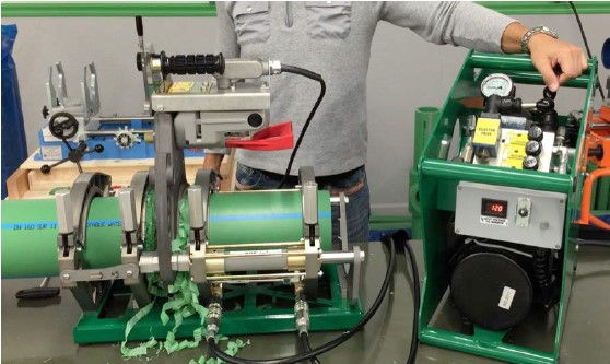
BUTT FUSION

Butt fusion is used to accomplish connections of 4” or larger pipes and/or fittings. There are many models of butt fusion machines, each designed for specific pipe size range. Some are light weight for use in overhead installations, other are designed to be used on the ground as part of a pre-fabrication station. To insure you have the proper equipment for the job, please consult with PESTAN support or with an approved PESTAN equipment manufacturer.
There are two main types of butt fusion machines, Manual and Hydraulic (shown in the photo above). The difference in the two is pressure regulation: one uses manual force, the other uses a hydraulic power unit. The basic principles of fusion is the same for both types of fusion machines. Before performing butt fusion, read the fusion machine manual. Familiarize yourself with the operation of the fusion machine and follow all safety measures and recommendations. Verify the sizes of the inserts are compatible with the pipe and/or fitting size. Secure the inserts into the machine clamps. Clean the heating plate with lint free, non-synthetic cloth or paper towel.
Plug the fusion machine and heating plate into the power source and verify the temperature of heating plate reached 410°F (210°C), with maximum variance of +/-15°F. Make sure power supply is sufficient for the machine used. Insufficient power supply can cause cold fusions that will fail. If using extension cords, insure that cord is capable of delivering the required power and that you are within a reasonable distance from the power supply. Cut the pipe to the desired length. Make sure to cut as squarely as possible.
Place pipes and/or fitting into the clamps of the fusion machine, leaving approximately 1” from the edge of the pipe to the clamp. Adjust second clamp of the fusion machine to accommodate length of the pipe/fitting. If there is ovality in the pipe/fitting, place the long side vertically, so the clamps help re-round the pipe.

Note: if two pipes are being fused, line up the print lines on both pipes. If print line is not available, line up the stripes on the pipe.
Insert Facer. Make sure facer is not touching the pipe and/or fitting, turn it on and let it reach full speed.

Slowly increase the pressure control valve until carriage with pipes and/or fittings move towards each other and trim until the jaws come in contact with the facer stops.
Note: if facer motor stalls, decrease the pressure.
When trimming is achieved, drive the carriage away from the facer and then turn the facer off. Remove facer and place it in the holder.
Clear shavings from the pipes and the fusion space. Clean faced ends of the pipe and/or fitting with the lint
free non-synthetic cloth or paper towel.
Inspect shavings ribbons for at least one complete ribbon from both ends. This ensures that the pipe faces are clean and parallel.

Slowly increase the pressure until the carriage starts moving, then back the pressure down until the carriage
is barely moving. This is your Drag Pressure.
Close the carriage, visually check for the vertical alignment of the faced ends. If needed, tighten the inside
clamp on the high side to bring ends into the alignment and re-face the pipe.
Note: Pen or other slim flat edged instrument can also be used to check if the ends are vertically aligned.

Once facing is completed and both faced ends are aligned, set the Fusion Pressure to recommended pressures depending on the pipe size, wall thickness and machine model. Fusion Pressures can be found in the tables above or online at www.pestanpipes.com. Bring pipe ends together to insure that pipe doesn’t slip in clamps. Open carriage with the space between faced ends with 2-3” gap and insert the heating plate. Bring the faced ends onto the heating plate using the Fusion Pressure.

Watch closely for the formation of the beads where the pipe/fitting touches the heating plate. When a thin line of melt appears all the way around the pipe, drop the pressure down to 0 if the machine has locking carriage, otherwise drop the pressure to Drag pressure and start measuring the required Heating Time.
Wait for the entire Heating Time to elapse (Table up above). Shift the fusion machine into fusion pressure. After reaching the proper Heating Time, Open the carriage and carefully remove the heating plate. Quickly (within 3 seconds) inspect heated ends for contamination, concave pipe/fitting face and a consistent melt bead.

After the inspection, use the Fusion Pressure to close the carriage and start the Cooling Time (table below).

Leave the fusion machine running for the entire Cooling Time. Depending on the type of fusion machine you
may need to periodically check the pressure gauge, and adjust to keep the required Fusion Pressure.

Note: Do not pour water onto the connecting to shorten the Cooling Time. If both ends of the pipes and/or fittings continues to be supported, then Cooling Times can be reduced by 50%.
After reaching Cooling Time, bring pressure to 0 and release pipes and or fittings from the clamps. Inspect the joint for any contamination, uniform bead size, no double-bead formation.
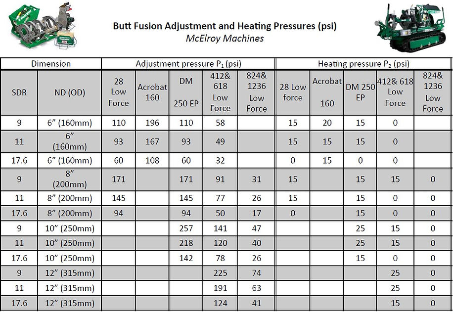
The following table gives the times for the heating phase, fusion phase and cooling phase of a butt fusion. The heating, Fusion and cooling times are based on the size and SDR of the pipe. These values do not change from one fusion machine to the next.

The second table includes that value from some of the commonly available machines in Pestan’s systems for quick reference. This data is based on information from the respective manufacturers of these tools. These pressures also depends on the size and SDR of the pipe. When using other fusion machines, the pressures P1, P2 and P3 must be adjusted. Following diagram shows physical meaning of parameters (times and pressures), which are used in first and second table in this section.


SHIPPING, STORAGE AND HANDLING
Shipping
It is the customer’s responsibility to verify the product against the packing slip and visually inspect it for damage. Variations in the shipment or any damaged product should be documented and reported to the Distributor.

Storage
PP-R(CT) pipe is shipped in 13’ and 19’ straight lengths which are packaged in plastic bags that help protect it from UV exposure and keep it clean. We recommend that the pipes remain in their protective packaging until ready for use.
The pipe should be stored on a flat surface. If storing the pipe on racks, it should have a minimum of four evenly spaced supports. We recommend you place plywood or a similar form of backing across the supports to prevent the pipe from deforming. Maximum stacking height for the pipe is 3ft.
Indoor storage of PP-R(CT) pipe is recommended. Avoid storage in areas where solvents, paints, glue or similar products are kept.
If stored outside for an extended period, keep the pipes in their UV Resistant bags and place them in a shaded area. If you are storing the pipe outside but covering them, use a light colored tarp. Black tarp is not recommended as it can cause heat damage. The warranty will be voided if the pipes are exposed to UV radiation for more than 6 months.

Handling
Proper handling of the pipe is necessary to prevent damage. By following a few precautions, you can insure the integrity of your system.
1. Protect the ends of the pipe. Dropping them on a hard surface or stepping on them can cause micro-fractures in the pipe wall.
2. If the pipe is dropped or crushed, check it for damage. Damages should be identified, marked and eliminated.
3. Cold weather makes the pipe less flexible and more susceptible to impact damage. Use caution when handling in cold temperature. Handling of PP-R(CT) products is not recommended in temperatures below -5°F.
4. Use caution when using a forklift to move the pipe. Do not drape the pipe over the fork. Instead, place the pipe on a pallet for support and then transport. When handling larger diameter pipes, do not insert the forks into the end of the pipe.
5. When shipping, load on a flat or supported surface and only strap in supported areas to prevent pipe deformation.
6. Keep the fittings in their original bags for ease of identification.